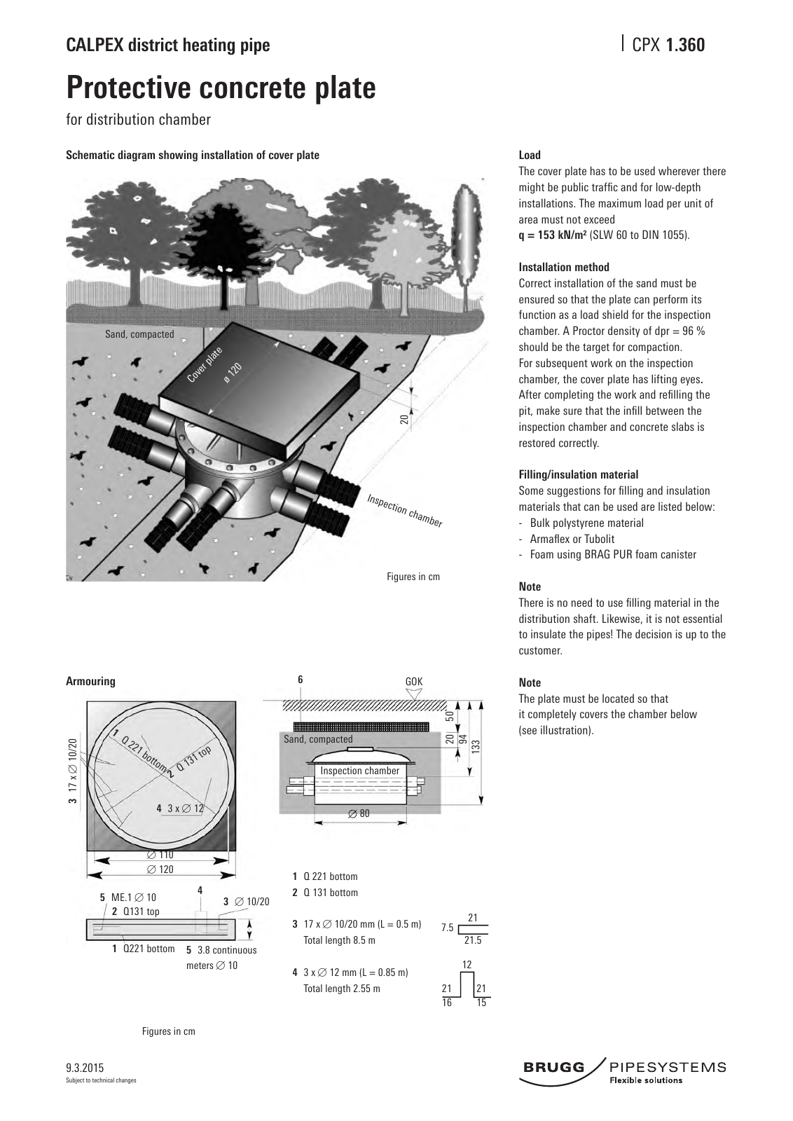
9 3 2015 CALPEX district heating pipe CPX Subject to technical changes Protective concrete plate for distribution chamber 1 360 Schematic diagram showing installation of cover plate Load The cover plate has to be used wherever there might be public traffic and for low depth installations The maximum load per unit of area must not exceed q 153 kN m SLW 60 to DIN 1055 Installation method Correct installation of the sand must be ensured so that the plate can perform its function as a load shield for the inspection chamber A Proctor density of dpr 96 should be the target for compaction For subsequent work on the inspection chamber the cover plate has lifting eyes After completing the work and refilling the pit make sure that the infill between the inspection chamber and concrete slabs is restored correctly Filling insulation material Some suggestions for filling and insulation materials that can be used are listed below Bulk polystyrene material Armaflex or Tubolit Foam using BRAG PUR foam canister Note There is no need to use filling material in the distribution shaft Likewise it is not essential to insulate the pipes The decision is up to the customer Note The plate must be located so that it completely covers the chamber below see illustration 20 Sand compacted Figures in cm GOK Sand compacted Inspection chamber 80 16 15 2121 12 21 21 5 7 5 4 3 x 12 110 120 3 10 20 2 Q131 top 1 Q221 bottom 5 ME 1 10 5 3 8 continuous meters 10 1 Q 221 bottom 2 Q 131 bottom 3 17 x 10 20 mm L 0 5 m Total length 8 5 m 4 3 x 12 mm L 0 85 m Total length 2 55 m 6 Figures in cm Armouring 4 Co ver pl ate ø 1 20 Inspection chamber 50 13 39420 1 Q 221 bottom 2 Q 13 1 to p 3 17 x 1 0 20
Hinweis: Dies ist eine maschinenlesbare No-Flash Ansicht.
Klicken Sie hier um zur Online-Version zu gelangen.
Klicken Sie hier um zur Online-Version zu gelangen.