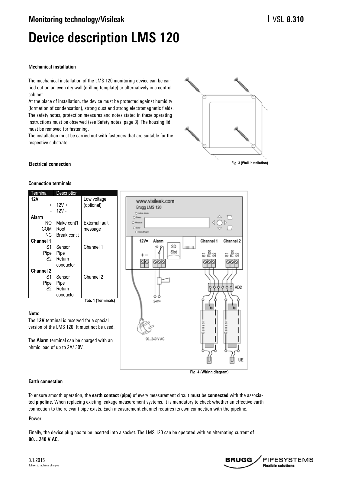
8 1 2015 Monitoring technology Visileak VSL Subject to technical changes Device description LMS 120 Mechanical installation The mechanical installation of the LMS 120 monitoring device can be car ried out on an even dry wall drilling template or alternatively in a control cabinet At the place of installation the device must be protected against humidity formation of condensation strong dust and strong electromagnetic fields The safety notes protection measures and notes stated in these operating instructions must be observed see Safety notes page 3 The housing lid must be removed for fastening The installation must be carried out with fasteners that are suitable for the respective substrate Fig 3 Wall installation Electrical connection Note The 12V terminal is reserved for a special version of the LMS 120 It must not be used The Alarm terminal can be charged with an ohmic load of up to 2A 30V Earth connection To ensure smooth operation the earth contact pipe of every measurement circuit must be connected with the associa ted pipeline When replacing existing leakage measurement systems it is mandatory to check whether an effective earth connection to the relevant pipe exists Each measurement channel requires its own connection with the pipeline Power Finally the device plug has to be inserted into a socket The LMS 120 can be operated with an alternating current of 90 240 V AC 3 2 Electrical connection 3 2 1 Connection terminals Terminal Description 12V 12V 12V Low voltage optional Alarm NO COM NC Make cont t Root Break cont t External fault message Channel 1 S1 Pipe S2 Sensor Pipe Return conductor Channel 1 Channel 2 S1 Pipe S2 Sensor Pipe Return conductor Channel 2 Tab 1 Ter minals Fig 4 Wiring diagram Connection termi als 8 310
Hinweis: Dies ist eine maschinenlesbare No-Flash Ansicht.
Klicken Sie hier um zur Online-Version zu gelangen.
Klicken Sie hier um zur Online-Version zu gelangen.