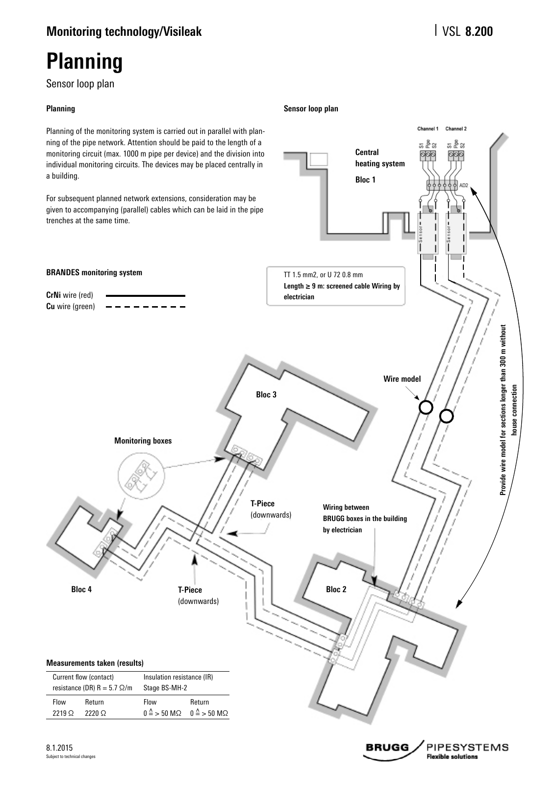
8 1 2015 Monitoring technology Visileak VSL Subject to technical changes Planning Sensor loop plan 8 200 Planning Planning of the monitoring system is carried out in parallel with plan ning of the pipe network Attention should be paid to the length of a monitoring circuit max 1000 m pipe per device and the division into individual monitoring circuits The devices may be placed centrally in a building For subsequent planned network extensions consideration may be given to accompanying parallel cables which can be laid in the pipe trenches at the same time Sensor loop plan Measurements taken results Current flow contact resistance DR R 5 7 Ω m Insulation resistance IR Stage BS MH 2 Flow 2219 Ω Return 2220 Ω Flow 0 50 MΩ Return 0 50 MΩ TT 1 5 mm2 or U 72 0 8 mm Length 9 m screened cable Wiring by electrician BRANDES monitoring system CrNi wire red Cu wire green Wiring between BRUGG boxes in the building by electrician Wire model Pr ov id e w ire m od el fo r s ec tio ns lo ng er th an 3 00 m w ith ou t ho us e co nn ec tio n Central heating system T Piece downwards T Piece downwards Bloc 1 Bloc 3 Bloc 2Bloc 4 Monitoring boxes
Hinweis: Dies ist eine maschinenlesbare No-Flash Ansicht.
Klicken Sie hier um zur Online-Version zu gelangen.
Klicken Sie hier um zur Online-Version zu gelangen.