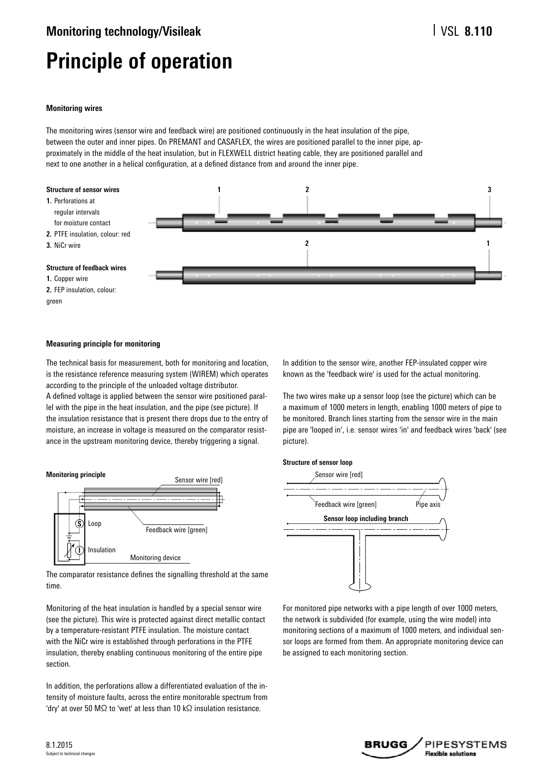
8 1 2015 Monitoring technology Visileak VSL Subject to technical changes Principle of operation Monitoring wires The monitoring wires sensor wire and feedback wire are positioned continuously in the heat insulation of the pipe between the outer and inner pipes On PREMANT and CASAFLEX the wires are positioned parallel to the inner pipe ap proximately in the middle of the heat insulation but in FLEXWELL district heating cable they are positioned parallel and next to one another in a helical configuration at a defined distance from and around the inner pipe Structure of sensor wires 1 Perforations at regular intervals for moisture contact 2 PTFE insulation colour red 3 NiCr wire Structure of feedback wires 1 Copper wire 2 FEP insulation colour green Measuring principle for monitoring The technical basis for measurement both for monitoring and location is the resistance reference measuring system WIREM which operates according to the principle of the unloaded voltage distributor A defined voltage is applied between the sensor wire positioned paral lel with the pipe in the heat insulation and the pipe see picture If the insulation resistance that is present there drops due to the entry of moisture an increase in voltage is measured on the comparator resist ance in the upstream monitoring device thereby triggering a signal The comparator resistance defines the signalling threshold at the same time Monitoring of the heat insulation is handled by a special sensor wire see the picture This wire is protected against direct metallic contact by a temperature resistant PTFE insulation The moisture contact with the NiCr wire is established through perforations in the PTFE insulation thereby enabling continuous monitoring of the entire pipe section In addition the perforations allow a differentiated evaluation of the in tensity of moisture faults across the entire monitorable spectrum from dry at over 50 MΩ to wet at less than 10 kΩ insulation resistance In addition to the sensor wire another FEP insulated copper wire known as the feedback wire is used for the actual monitoring The two wires make up a sensor loop see the picture which can be a maximum of 1000 meters in length enabling 1000 meters of pipe to be monitored Branch lines starting from the sensor wire in the main pipe are looped in i e sensor wires in and feedback wires back see picture For monitored pipe networks with a pipe length of over 1000 meters the network is subdivided for example using the wire model into monitoring sections of a maximum of 1000 meters and individual sen sor loops are formed from them An appropriate monitoring device can be assigned to each monitoring section Monitoring principle Sensor wire red Feedback wire green Monitoring device Insulation LoopS I Structure of sensor loop Feedback wire green Sensor wire red Pipe axis Sensor loop including branch 1 2 3 2 1 8 110
Hinweis: Dies ist eine maschinenlesbare No-Flash Ansicht.
Klicken Sie hier um zur Online-Version zu gelangen.
Klicken Sie hier um zur Online-Version zu gelangen.